jmann
This material has been posted before in numerous places so I thought I'd try to consolidate it into one place.
I'd like to thank all those folks that contributed in other threads and other forums.
Instructions for 06 to 07 Speedo Conversion
(V1.0.4)
The 06 to 07 conversion process is relatively easy and can be made easier by using conversion cables. Essentially all that is required is to:
* Provide a feed to the new speedo from the Tachometer line of the ECU. The 06 model has this line coming out via the centre pin of it's own 3 pin plug.
So all that is necessary is to run a line from that plug to the appropriate pin on the 12-pin connector. Ignore the other two wires.
* Provide a direct feed from the Water Temperature Sensor to the 12-pin connector rather than from the ECU as the 06 model does.
* This requires a new 3 pin Water Temperature Sensor, connector and a new feed wire.
* Linking in the Alarm LED circuit if not already connected.
For my bikes I wanted to leave the original connectors intact so I constructed 2 cables that convert between the different connectors on the 06 and 07 harnesses and allow for two pin relocations. In my diagram:
* Red boxes represent additional connectors.
* Green lines represent new wiring.
* C_xx/y represents the connectors required. The coding is explained below.
The positions used on the connectors do not necessarily reflect the actual positions on the harnesses unless indicated/numbered.
Generally, the original path should be maintained.
If conversion cables (with appropriate KTM connectors) are not made everything remains the same except that some
cable splicing or soldering needs to be done.
KTM connectors all have the same part number (000700000) followed by the 2 character code. Both halves of the 12-pole connectors are for example, CC and CI, thus the part numbers are 000700000CC and 000700000CI. All connector letters are uppercase. In my diagram I have used the KTM convention for labelling connectors. C_BE/3 means: Connector, Type BE, 3-pole and the part number would be 000700000BE.
Photographs (All photographs are at the end of this document)
Photo 1 shows the 06 12-pin socket.
Photo 2 shows the 06 Alarm LED connector.
Photo 3 shows 06 the Tacho plug.
Photo 4 shows the 07 Front Headlight Harness and its connectors.
Photo 5 shows a 07 Speedo with the power on.
Photo 6 shows the main converter cable and the alarm LED converter cable.
Photo 7 shows the 07 headlight end of the 12-pin converter cable.
Photo 8 shows all converters assembled.
Photo 9 shows Bert's Setup with converter cables.
Photo 10 shows Bert's Completed Mask.
Steps
* Buy the required parts (listed below).
* Connect the Alarm Led cable using a converter cable.
* Plug the 07 Speedo via the 07 Front Headlight Harness into the original 12-pin socket. Nothing else needs to be plugged in other than the Alarm LED.
Once plugged in, turn on the ignition and see if the speedo lights up as per Photo 5. If it lights up proceed otherwise something is wrong.
This is a good first step especially if the speedo is secondhand.
* Install the 07 Water Temperature Sensor (details below). This sensor requires a new connector and a feed from pin 3 to the 07 speedo via pin 9 of the 12-pin connector at the speedo end. On the 06 bike connector, pin 9 is occupied by the feed from the ECU. The converter system just terminates (does not connect) the 06 pin 9 (blue/brown) and connects the new cable to the new pin 9 labelled blue/orange in my diagram to match the 07 end. The other two wires from the Water Temperature Sensor can be left connected as they were originally. A 1-pin connector can be inserted into the new cable at the headlight end to allow the adapter to be easily removed. If you have problems with this connector the F1 light will show an error with the ignition on.
* Connect the Tachometer feed which is the blue/white cable on the 06 3-pin connector to the 07 speedo via pin 8 of the 12-pin connectors (blue/white) on the speedo end. Pin 8 was empty on the 06 connector so this could be used or the converter connectors used.
* All functions of the 07 speedo should now work.
The 07 Front Headlight harness has connectors for the front indicators. These were not present on the 06 bike so connectors can be added if required.
The 07 Front Headlight harness has a connector for the Ambient Air Temperature Sensor. This can be connected if required otherwise the speedo will always show -30. Bert believes these will do the job but I haven't tried one yet:
http://www.ebay.com/itm/1pcs-NTC-10K-10 ... 0759600535
Installing the 07 Water Temperature Sensor (WTS)
Bert and others claim that “Replacing the water temp sensor is a PINA” this is an understatement!!! The problem is that the WTS hidden is behind the frame tube in the left hand side of the rear cylinder head. Getting it out is not easy but it can be done with a cut off tube spanner or similar. Intrepid mechanics may just unscrew it while other less adventurous types may wish to drain the coolant or at least partially drain the coolant. Tilting the bike over will reduce the spillage if the non-drain method is chosen.
Bert has discovered that it is possible to disassemble the 2-pin 06 connector for the WTS. Doing this allows the two original cables and connector clips to be used in the 07 3-pin connector thus leaving the original wiring intact. To do so remove the inner rubber seal that surrounds the fluorescent centre piece with a watchmakers screwdriver then depress the retaining tang that stops the connector socket from pulling out. Once out, use the two wires (complete with the connector socket) in the 3-pin socket on the appropriate pins. A new wire is then run from the third pin up to pin 9 of the 12-pin connector in the headlight shell.
Major Parts List
1x61108001000 HEAD LIGHT MASK LEFT 07
1x61108002000 HEAD LIGHT MASK RIGHT 07
1x6110800300074A MASK SPOILER LEFT ORANGE 07
1x6110800400074A MASK SPOILER RIGHT ORANGE 07
1x61108065000 WIND SHIELD 07
1x61114069000 SPEEDOMETER 07
1x61108005000 SPEEDOMETER BRACKET 07
1x61111079000 WIRING HARNESS FRONT 07
1x75035047000 TEMPERATURE SENSOR WATER 07
1x61111018000 AMBIENT AIR TEMPERATURE SENSOR 07 (OPTIONAL)
Screws Etc
3x58214069051 RUBBER GROMMET
4x0021050003 WASHER
4x60008008050 BLIND PLUG-IN NUT
4x60008046000 SPECIAL WASHER
1x0016050253 SCREW FOR PLASTIC
1x61103088000 EXPANDING RIVET PA6 BLACK
7x0081050121 SCREW FOR PLASTIC
1x0738060121 OVAL HEAD SCREW
4x0019050201 COUNTERSUNK SCREW
Electrical Connectors
1x000700000CI 12-pin Connector (Capital i)
1x000700000CC 12-pin Connector
1x000700000EC 3-pin Connector Water Temp Sensor
1x000700000BE 3-pin Tachometer Cable Connector
2x000700000CW 2-pin Connector Front Indicators
1x000700000BV 2-pin Connector Alarm LED
1x000700000AG 3-pin Connector Alarm LED
Wiring Diagram

Photo 1 shows the 06 12-pin socket.
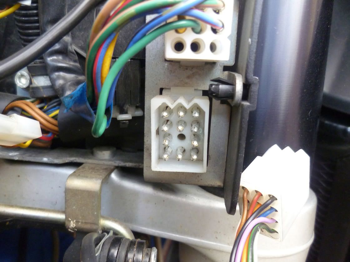
Photo 2 shows the 06 Alarm LED connector.

Photo 3 shows 06 the Tacho plug.

Photo 4 shows the 07 Front Headlight Harness and its connectors.

Photo 5 shows a 07 Speedo with the power on.
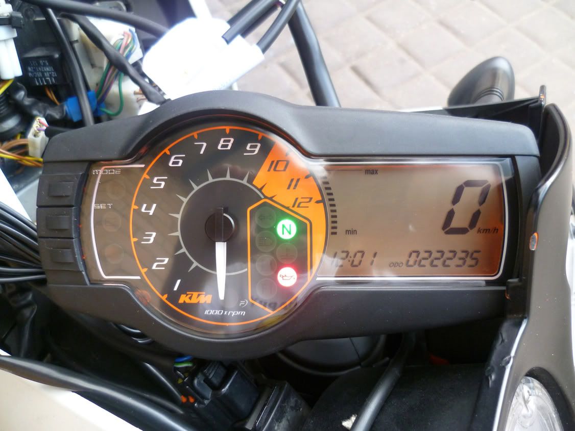
Photo 6 shows the main converter cable and the alarm LED converter cable.
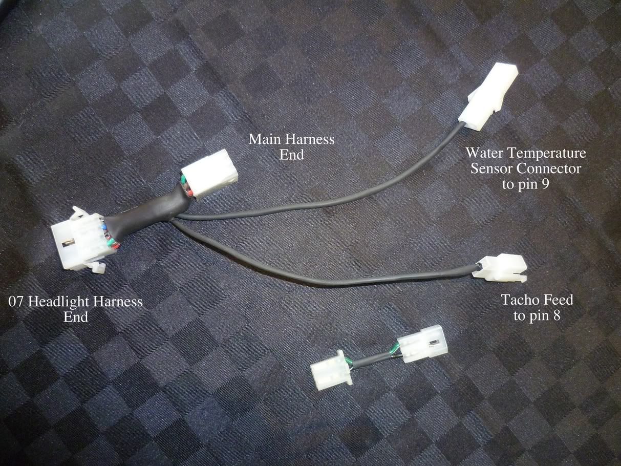
Photo 7 shows the 07 headlight end of the 12-pin converter cable.
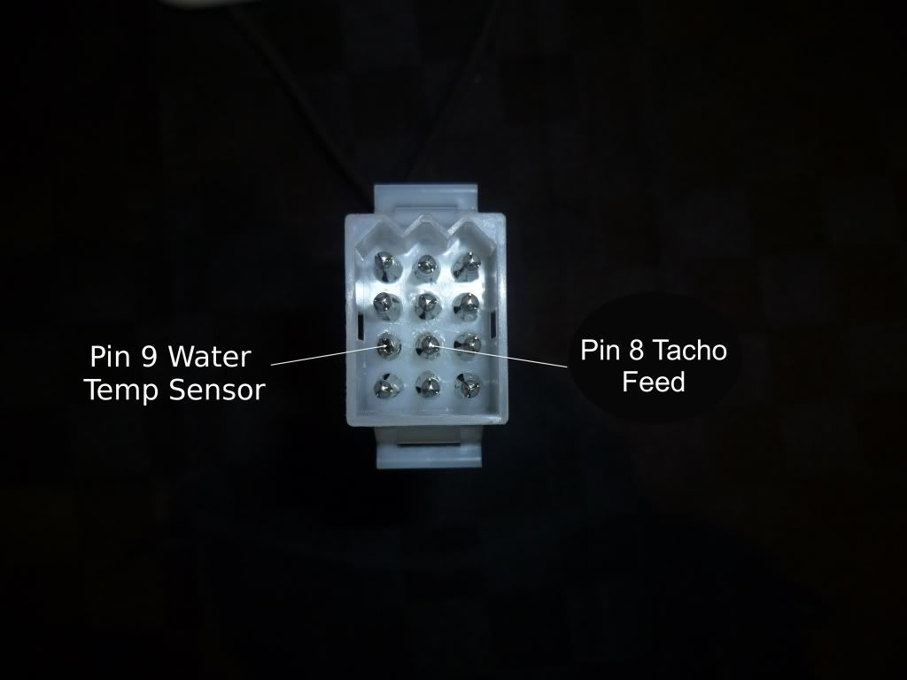
Photo 8 shows all converters assembled.
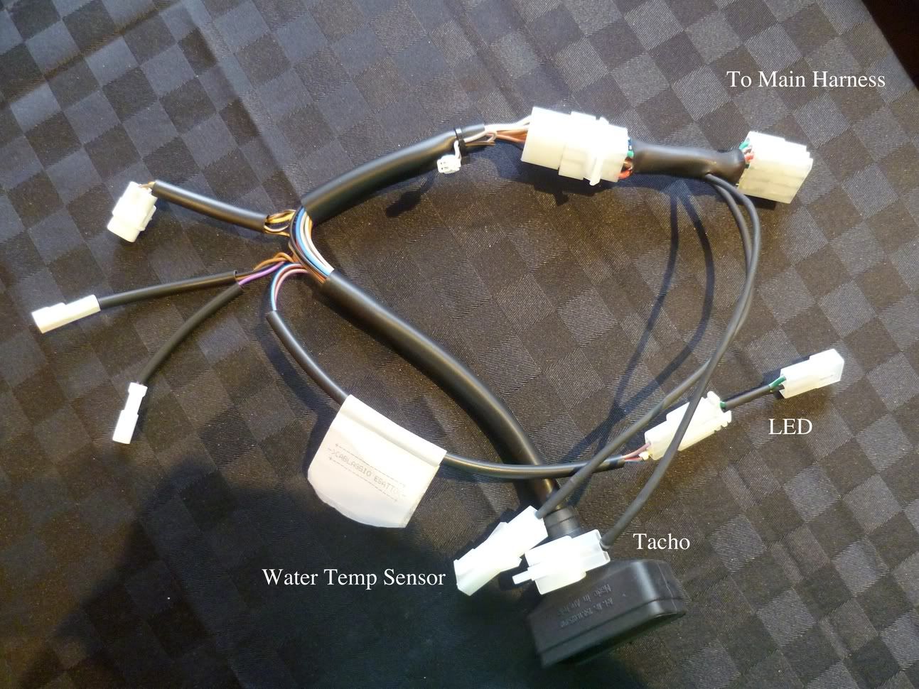
Photo 9 shows the tool Bert made to get the Water Temperature Sensor out.

Photo 10 shows Bert's Setup with converter cables.

Photo 11 shows Bert's Completed Mask.

Modification History
V1.0.2 (With thanks to Bert)
Added this section as I realised some errors would creep in and need fixing.
Added/modified clarifying sentences.
Corrected the EC entry in the parts list.
Corrected the missing letter in the parts list.
Changed all occurrences of Cl to CI (capital i). Removed a Cl sentence.
Indicated pin 8 on 06 12-pin connector is empty.
Fixed wiring diagram to reflect the 3-pin connector for Alarm LED as supplied on the 07 Front Wiring Harness.
V1.0.3 (With thanks to Bert)
Found another reference to that incorrect connector – replaced with (Capital i).
V1.0.4 (21st May 2012 With thanks to Bert)
Changed my wiring diagram to have the Tacho wire on the center pin. This more accurately reflects the physical layout of the connector.
The KTM wiring diagram is slightly confusing as it shows the pins as 132 order. The blue and white wire (the only one used) is on the centre pin.
Changed the Water Temperature Sensor layout to use the disassembled old connector and a new single wire to the 12-pin plug.
Also incorporated a generic 1-pin connector which has a well insulated end closest to the Water Temperature Sensor.
This is so the headlight can be reverted back to a 06 system whilst leaving the Water Temperature Sensor in place.
Added screws Etc. to parts list.
26th May 2012 added a link to possible non-OEM temperature sensor. (Thanks Bert again).
Added a section on installing the 07 Water Temperature Sensor.
I'd like to thank all those folks that contributed in other threads and other forums.
Instructions for 06 to 07 Speedo Conversion
(V1.0.4)
The 06 to 07 conversion process is relatively easy and can be made easier by using conversion cables. Essentially all that is required is to:
* Provide a feed to the new speedo from the Tachometer line of the ECU. The 06 model has this line coming out via the centre pin of it's own 3 pin plug.
So all that is necessary is to run a line from that plug to the appropriate pin on the 12-pin connector. Ignore the other two wires.
* Provide a direct feed from the Water Temperature Sensor to the 12-pin connector rather than from the ECU as the 06 model does.
* This requires a new 3 pin Water Temperature Sensor, connector and a new feed wire.
* Linking in the Alarm LED circuit if not already connected.
For my bikes I wanted to leave the original connectors intact so I constructed 2 cables that convert between the different connectors on the 06 and 07 harnesses and allow for two pin relocations. In my diagram:
* Red boxes represent additional connectors.
* Green lines represent new wiring.
* C_xx/y represents the connectors required. The coding is explained below.
The positions used on the connectors do not necessarily reflect the actual positions on the harnesses unless indicated/numbered.
Generally, the original path should be maintained.
If conversion cables (with appropriate KTM connectors) are not made everything remains the same except that some
cable splicing or soldering needs to be done.
KTM connectors all have the same part number (000700000) followed by the 2 character code. Both halves of the 12-pole connectors are for example, CC and CI, thus the part numbers are 000700000CC and 000700000CI. All connector letters are uppercase. In my diagram I have used the KTM convention for labelling connectors. C_BE/3 means: Connector, Type BE, 3-pole and the part number would be 000700000BE.
Photographs (All photographs are at the end of this document)
Photo 1 shows the 06 12-pin socket.
Photo 2 shows the 06 Alarm LED connector.
Photo 3 shows 06 the Tacho plug.
Photo 4 shows the 07 Front Headlight Harness and its connectors.
Photo 5 shows a 07 Speedo with the power on.
Photo 6 shows the main converter cable and the alarm LED converter cable.
Photo 7 shows the 07 headlight end of the 12-pin converter cable.
Photo 8 shows all converters assembled.
Photo 9 shows Bert's Setup with converter cables.
Photo 10 shows Bert's Completed Mask.
Steps
* Buy the required parts (listed below).
* Connect the Alarm Led cable using a converter cable.
* Plug the 07 Speedo via the 07 Front Headlight Harness into the original 12-pin socket. Nothing else needs to be plugged in other than the Alarm LED.
Once plugged in, turn on the ignition and see if the speedo lights up as per Photo 5. If it lights up proceed otherwise something is wrong.
This is a good first step especially if the speedo is secondhand.
* Install the 07 Water Temperature Sensor (details below). This sensor requires a new connector and a feed from pin 3 to the 07 speedo via pin 9 of the 12-pin connector at the speedo end. On the 06 bike connector, pin 9 is occupied by the feed from the ECU. The converter system just terminates (does not connect) the 06 pin 9 (blue/brown) and connects the new cable to the new pin 9 labelled blue/orange in my diagram to match the 07 end. The other two wires from the Water Temperature Sensor can be left connected as they were originally. A 1-pin connector can be inserted into the new cable at the headlight end to allow the adapter to be easily removed. If you have problems with this connector the F1 light will show an error with the ignition on.
* Connect the Tachometer feed which is the blue/white cable on the 06 3-pin connector to the 07 speedo via pin 8 of the 12-pin connectors (blue/white) on the speedo end. Pin 8 was empty on the 06 connector so this could be used or the converter connectors used.
* All functions of the 07 speedo should now work.
The 07 Front Headlight harness has connectors for the front indicators. These were not present on the 06 bike so connectors can be added if required.
The 07 Front Headlight harness has a connector for the Ambient Air Temperature Sensor. This can be connected if required otherwise the speedo will always show -30. Bert believes these will do the job but I haven't tried one yet:
http://www.ebay.com/itm/1pcs-NTC-10K-10 ... 0759600535
Installing the 07 Water Temperature Sensor (WTS)
Bert and others claim that “Replacing the water temp sensor is a PINA” this is an understatement!!! The problem is that the WTS hidden is behind the frame tube in the left hand side of the rear cylinder head. Getting it out is not easy but it can be done with a cut off tube spanner or similar. Intrepid mechanics may just unscrew it while other less adventurous types may wish to drain the coolant or at least partially drain the coolant. Tilting the bike over will reduce the spillage if the non-drain method is chosen.
Bert has discovered that it is possible to disassemble the 2-pin 06 connector for the WTS. Doing this allows the two original cables and connector clips to be used in the 07 3-pin connector thus leaving the original wiring intact. To do so remove the inner rubber seal that surrounds the fluorescent centre piece with a watchmakers screwdriver then depress the retaining tang that stops the connector socket from pulling out. Once out, use the two wires (complete with the connector socket) in the 3-pin socket on the appropriate pins. A new wire is then run from the third pin up to pin 9 of the 12-pin connector in the headlight shell.
Major Parts List
1x61108001000 HEAD LIGHT MASK LEFT 07
1x61108002000 HEAD LIGHT MASK RIGHT 07
1x6110800300074A MASK SPOILER LEFT ORANGE 07
1x6110800400074A MASK SPOILER RIGHT ORANGE 07
1x61108065000 WIND SHIELD 07
1x61114069000 SPEEDOMETER 07
1x61108005000 SPEEDOMETER BRACKET 07
1x61111079000 WIRING HARNESS FRONT 07
1x75035047000 TEMPERATURE SENSOR WATER 07
1x61111018000 AMBIENT AIR TEMPERATURE SENSOR 07 (OPTIONAL)
Screws Etc
3x58214069051 RUBBER GROMMET
4x0021050003 WASHER
4x60008008050 BLIND PLUG-IN NUT
4x60008046000 SPECIAL WASHER
1x0016050253 SCREW FOR PLASTIC
1x61103088000 EXPANDING RIVET PA6 BLACK
7x0081050121 SCREW FOR PLASTIC
1x0738060121 OVAL HEAD SCREW
4x0019050201 COUNTERSUNK SCREW
Electrical Connectors
1x000700000CI 12-pin Connector (Capital i)
1x000700000CC 12-pin Connector
1x000700000EC 3-pin Connector Water Temp Sensor
1x000700000BE 3-pin Tachometer Cable Connector
2x000700000CW 2-pin Connector Front Indicators
1x000700000BV 2-pin Connector Alarm LED
1x000700000AG 3-pin Connector Alarm LED
Wiring Diagram
Photo 1 shows the 06 12-pin socket.
Photo 2 shows the 06 Alarm LED connector.
Photo 3 shows 06 the Tacho plug.
Photo 4 shows the 07 Front Headlight Harness and its connectors.
Photo 5 shows a 07 Speedo with the power on.
Photo 6 shows the main converter cable and the alarm LED converter cable.
Photo 7 shows the 07 headlight end of the 12-pin converter cable.
Photo 8 shows all converters assembled.
Photo 9 shows the tool Bert made to get the Water Temperature Sensor out.
Photo 10 shows Bert's Setup with converter cables.
Photo 11 shows Bert's Completed Mask.
Modification History
V1.0.2 (With thanks to Bert)
Added this section as I realised some errors would creep in and need fixing.
Added/modified clarifying sentences.
Corrected the EC entry in the parts list.
Corrected the missing letter in the parts list.
Changed all occurrences of Cl to CI (capital i). Removed a Cl sentence.
Indicated pin 8 on 06 12-pin connector is empty.
Fixed wiring diagram to reflect the 3-pin connector for Alarm LED as supplied on the 07 Front Wiring Harness.
V1.0.3 (With thanks to Bert)
Found another reference to that incorrect connector – replaced with (Capital i).
V1.0.4 (21st May 2012 With thanks to Bert)
Changed my wiring diagram to have the Tacho wire on the center pin. This more accurately reflects the physical layout of the connector.
The KTM wiring diagram is slightly confusing as it shows the pins as 132 order. The blue and white wire (the only one used) is on the centre pin.
Changed the Water Temperature Sensor layout to use the disassembled old connector and a new single wire to the 12-pin plug.
Also incorporated a generic 1-pin connector which has a well insulated end closest to the Water Temperature Sensor.
This is so the headlight can be reverted back to a 06 system whilst leaving the Water Temperature Sensor in place.
Added screws Etc. to parts list.
26th May 2012 added a link to possible non-OEM temperature sensor. (Thanks Bert again).
Added a section on installing the 07 Water Temperature Sensor.

